OpenShift Virtualization Networking - The Overview
December 29, 2025
Updated Dec 30, 2025
-
![]() Thomas Jungbauer
-
9 min read
(1887 words)
Thomas Jungbauer
-
9 min read
(1887 words)
It’s time to dig into OpenShift Virtualization. You read that right, OpenShift Virtualization, based on kubevirt allows you to run Virtual Machines on top of OpenShift, next to Pods. If you come from a pure Kubernetes background, OpenShift Virtualization can feel like stumbling into a different dimension. In the world of Pods, we rarely care about Layer 2, MAC addresses, or VLANs. The SDN (Software Defined Network) handles the magic and we are happy.
But Virtual Machines are different….
They are needy creatures. They often refuse to live in the bubble of the default Pod network. They want to talk to the external Oracle database on the bare metal server next door, they need a static IP from the corporate range, or they need to be reachable via a specific VLAN. Networking is a key part of the Virtualization story and we need to master it.
To achieve this, we need to understand two tools: NMState Operator and Multus.
In this guide, I will try to discuss some of the basics for "Multihomed Nodes" and look at the three main ways to connect your VMs to the outside world.
Who does what: NMState vs. Multus
Before we look at YAML, we need to clear up a common confusion. Who does what?
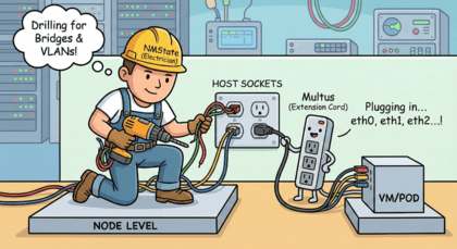
Think of your OpenShift Node as a house.
NMState (The Electrician): This operator works on the Node (Host) level. It drills holes in the walls, lays the physical cables, and installs the wall sockets. In technical terms: It configures Bridges, Bonds, and VLANs on the Linux OS of the worker nodes.
Multus (The Extension Cord): This CNI plugin works on the VM/Pod level. It plugs the VM into the socket that NMState created. It allows a VM to have more than one network interface (eth0, eth1, etc.).
You usually need both. First, NMState builds the bridge. Then, Multus connects the VM to it.
NMState Operator Installation
While Multus is installed by default, NMState is not. You need to install the Operator first.
To install the NMState Operator, you can use the Web UI or the CLI. For the Web UI, you can use the following steps:
In the OpenShift Web Console, navigate to Operators → OperatorHub (or Ecosystem → Software Catalog in version 4.20+).
In the OperatorHub, search for NMState and select the Operator from the list.
Click on the NMState Operator and click on the Install button.
Select the Install button to install the Operator.
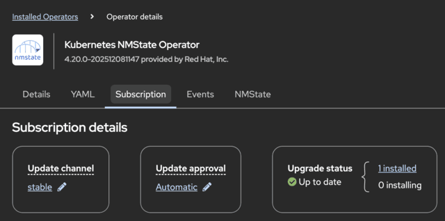
After the Operator is installed, you can check the status of the Operator in the Installed Operators view.
Once done you will need to create an instance of the NMState Operator. Simply create the following resource:
apiVersion: nmstate.io/v1
kind: NMState
metadata:
  name: nmstate
spec:
  probeConfiguration:
    dns:
      host: root-servers.net
NMState Operator Resource Types
The NMState Operator provides the three custom resource types to manage the node networking:
NodeNetworkState (NNS) → The "As-Is" State:
This is an automatically generated report of the current status. It effectively tells you: "On Server 1, I currently see Network Card A and B, and IP address X is configured."
Purpose: To verify the current reality on the ground before you make changes.
NodeNetworkConfigurationPolicy (NNCP) → The "To-Be" State (The Blueprint):
This is the most critical resource. This resource is used to configure the network on the node. Here you tell the cluster that "I want a bridge named br1 to exist on all servers, and it must be connected to port ens4."
The operator will try to configure this configuration across your nodes.
NodeNetworkConfigurationEnactment (NNCE) → The Result report:
This resource is created autoamtically after the NNCP (the blueprint) has been created.
It resports back: This resource is used to enact the network configuration on the node.
It reports back on the execution: "Success! The bridge has been built," or "Failure! Cable not found."
With NMState in place, we can now start to configure the network on the node.
Part 1: Building the Bridge (NMState)
By default, Virtual Machines (VMs) are connected to the default pod network of the cluster as any other Pod. Using this network, the VM can communicate with other resources inside the cluster, or any resources that are reachable through the node network. Sometimes the VM needs a connection to a different network. In such a case you must connect the VM to an additional network. The VM will be configured with an additional network interface and is considered as multihomed VM.
To connect a VM to the physical network, we first need a bridge on the worker nodes. A bridge forwards packets between connected interfaces, similar to a network switch. We have two choices: Linux Bridge or OVS (Open vSwitch) Bridge.
Linux Bridge: The sturdy, wooden bridge. Simple, robust, standard Linux kernel tech. Use this for 90% of your use cases (Static IPs, simple VLAN access).
OVS Bridge: The magical, floating bridge. Complex, programmable, supports SDN logic. Use this only if you need advanced tunneling or integration with OVN policies on the physical interface.
Let’s create a standard Linux Bridge called br1 on all our worker nodes, attached to physical interface ens4.
We do this by applying a NodeNetworkConfigurationPolicy (NNCP).
apiVersion: nmstate.io/v1
kind: NodeNetworkConfigurationPolicy
metadata:
  name: br1-policy
spec:
  nodeSelector:
    node-role.kubernetes.io/worker: "" (1)
  desiredState:
    interfaces:
    - name: br1 (2)
      description: Linux bridge linked to ens4 (3)
      type: linux-bridge (4)
      state: up (5)
      ipv4:
        dhcp: true (6)
        enabled: true
      bridge: (7)
        options:
          stp:
            enabled: false
        port: (8)
- name: ens4| 1 | Apply to all worker nodes. If omitted, the policy will be applied to all nodes. |
| 2 | Name of the bridge |
| 3 | Description of the bridge |
| 4 | Type of the bridge (linux-bridge) |
| 5 | State of the bridge (up) |
| 6 | DHCP is enabled for the bridge (true) |
| 7 | Options for the bridge |
| 8 | Port of the bridge (ens4) |
| Setting an interface to absent or deleting an NNCP resource does not restore the previous configuration. A cluster administrator must define a policy with the previous configuration to restore settings. |
Part 2: Defining the NetworkAttachmentDefinition (NAD)
Now that the bridge br1 exists on the nodes, we need to tell OpenShift how to use it. We do this with a NetworkAttachmentDefinition (NAD).
There are three distinct "Types" of networks you can define in a NAD.
1. The Linux Bridge (CNI-Plugin)
Linux bridges and OVS bridges both connect VMs to additional networks. A Linux bridge offers a simple, stable and sturdy solution and is well established. The OVS bridge on the other hand provides an advanced feature set for software-defined networks and is more challenging to troubleshoot.
Use Case: Direct Layer 2 connection to the physical network.
Behavior: The VM is practically "on the wire" of your datacenter. It can do DHCP with your corporate router.
apiVersion: k8s.cni.cncf.io/v1
kind: NetworkAttachmentDefinition
metadata:
  name: bridge-network
  namespace: my-vm-namespace
spec:
  config: '{
    "cniVersion": "0.3.1",
    "name": "bridge-network",
    "type": "bridge", (1)
    "bridge": "br1", (2)
    "ipam": {
        "type": "dhcp"
    }
}'| 1 | Type of the network (bridge) |
| 2 | Name of the bridge (br1) |
| type: "bridge" refers to the CNI plugin that utilizes the Linux Bridge we created earlier. |
A note on IPAM (IP Address Management)
You might have noticed the "ipam" section in the NAD examples. You have three main choices there:
dhcp: Passes DHCP requests to the physical network (requires an external DHCP server).
static: You manually define IPs in the VM config (hard work).
whereabouts: A "Cluster-wide DHCP" for private networks. Perfect for the OVN L2 Overlay scenario where no external DHCP exists.
2. OVN Kubernetes L2 Overlay
A switched (layer 2) topology network interconnects workloads through a cluster-wide logical switch. This configuration allows East-West traffic only (packets between Pods within a cluster).
Use Case: You need a private network between your VMs (East-West traffic only), but you don’t want them to talk to the physical network.
Behavior: It creates a Geneve tunnel (like VXLAN) over the network.
apiVersion: k8s.cni.cncf.io/v1
kind: NetworkAttachmentDefinition
metadata:
  name: private-overlay
  namespace: my-vm-namespace
spec:
  config: '{
    "cniVersion": "0.4.0",
    "name": "private-overlay",
    "type": "ovn-k8s-cni-overlay",
    "topology": "layer2", (1)
    "netAttachDefName": "my-vm-namespace/private-overlay" (2)
}'| 1 | Topology of the network (layer2) |
| 2 | NetworkAttachmentDefinition name (my-vm-namespace/private-overlay) |
A pod with the annotation k8s.v1.cni.cncf.io/networks: private-overlay will be connected to the private-overlay network.
3. OVN Kubernetes Secondary Localnet
OVN-Kubernetes also supports a localnet topology for secondary networks. This type creates a connection between a secondary network and a physical network, allowing VMs to communicate with destinations that are outside of the cluster. You must map the secondary network to the OVS bridge on the node. This is done by using a NodeNetworkConfigurationPolicy resource.
Use Case: You want to connect to the physical network (like the Linux Bridge), but you want to leverage OVN features (like NetworkPolicies) on that traffic.
Behavior: Uses Open vSwitch mapping to connect the OVN logic to the physical port.
Let’s create the bridge mapping by applying the following NodeNetworkConfigurationPolicy resource:
apiVersion: nmstate.io/v1
kind: NodeNetworkConfigurationPolicy
metadata:
  name: br0-ovs
spec:
  nodeSelector:
    node-role.kubernetes.io/worker: "" (1)
  desiredState:
    interfaces:
    - name: br0-ovs (2)
      description: OVS bridge with ens4 as a port
      type: ovs-bridge (3)
      state: up
      ipv4:
        dhcp: true
        enabled: true
      bridge:
        options:
          stp: true
        port:
        - name: ens4 (4)
    ovn:
      bridge-mappings:
      - localnet: br0-network (5)
        bridge: br0-ovs (6)
state: present| 1 | Apply to all worker nodes. If omitted, the policy will be applied to all nodes. |
| 2 | Name of the bridge |
| 3 | Type of the bridge (ovs-bridge) |
| 4 | Port of the bridge (ens4) |
| 5 | Localnet network name (br0-network) |
| 6 | OVS bridge name (br0-ovs) |
Now let’s create the NetworkAttachmentDefinition for the localnet network so that VMs can connect to it. This NAD is created in the namespace of the VM.
| If the NAD is created in the default namespace, the configuration will be available to all namespaces. |
apiVersion: k8s.cni.cncf.io/v1
kind: NetworkAttachmentDefinition
metadata:
  name: ovn-localnet
  namespace: my-vm-namespace
spec:
  config: '{
    "cniVersion": "0.4.0",
    "name": "ovn-localnet", (1)
    "type": "ovn-k8s-cni-overlay", (2)
    "topology": "localnet", (3)
    "netAttachDefName": "my-vm-namespace/br0-network" (4)
}'| 1 | Name of the network (ovn-localnet) |
| 2 | Type of the network (ovn-k8s-cni-overlay) |
| 3 | Topology of the network (localnet) |
| 4 | Reference to the localnet mapping name defined in the NNCP (my-vm-namespace/br0-network) |
Part 3: Connecting the VM
Finally, we have our "socket" (the NAD). Let’s plug the VM in. In your VirtualMachine manifest, you add the network to the spec.
This can be done via the Web Console or via the CLI.
Via the Web Console:
In the OpenShift Web Console, navigate to Virtualization → VirtualMachines.
Click on the VM you want to connect to the network.
Select the "Configuration" tab
Select "Network"
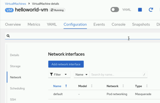
Click "Add network interface"
In the Popup enter a name for the interface
Model keep as "virtio"
On the "Network" select the NAD you created in the previous step.
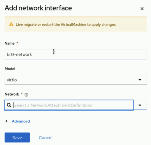
Click "Save"
The VM will now have a Pending state. This is because the VM is waiting for a migration to activate the new network interface.
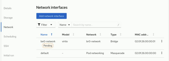
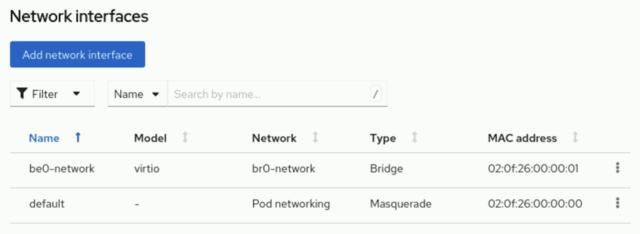
In the action menu you can select "Migrate" > "Compute" to start the migration process. After a while the new NIC will be active.
Via the CLI:
Here is a VM connected to the Linux Bridge NAD we created in step 1:
apiVersion: kubevirt.io/v1
kind: VirtualMachine
metadata:
  name: helloworld-vm
  namespace: my-vm-namespace
spec:
  template:
    spec:
      domain:
        devices:
          interfaces:
            - name: default
              masquerade: {} (1)
            - name: br0-network
              bridge: {} (2)
      networks:
        - name: default
          pod: {}
        - name: br0-network (3)
          multus:
networkName: br0-network (4)| 1 | The standard Pod Network |
| 2 | Our new connection |
| 3 | The NAD name |
| 4 | The NAD name |
Related Articles
Copyright © 2020 - 2026 Toni Schmidbauer & Thomas Jungbauer
Discussion
Comments are powered by GitHub Discussions. To participate, you'll need a GitHub account.
By loading comments, you agree to GitHub's Privacy Policy. Your data is processed by GitHub, not by this website.